Wiring scheme of one lamp
Here is the wiring scheme for one receiving lamp:

Tip: The pinout of the Arduino Nano can vary depending on the model, so be wary when using the pinout of the Arduino Nano in the image above. You can usually identify the pins directly on the Arduino itself.
Under /wiring/wiring_nRF24L01.txt you can find the textual wiring scheme to connect the Arduino Nano to the nRF24L01 module:
nRF24L01 -> Arduino wiring: GND -> GND CE -> D10 SCK -> D13 MISO -> D12 VCC -> 3.3V (DO NOT USE 5V !!!) CSN -> D9 MOSI -> D11
Here’s the pinout of the nRF24L01 module we used:

Wiring scheme of the HDMI box
Here is the wiring scheme for the HDMI box:
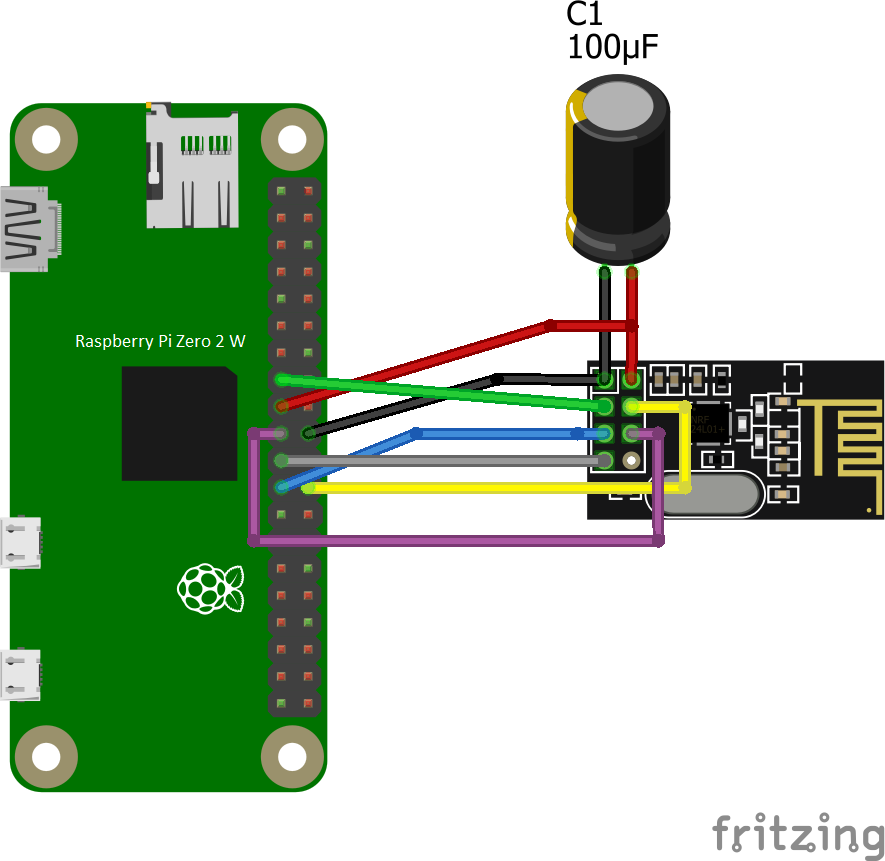
In the 'wiring' folder, you can also find the pinout for the Raspberry Pi Zero 2 W:

Besides connecting the nRF24L01 module to the Raspberry Pi, you will need to connect several other cables as well:
- Plug the micro USB power adapter into the PWR IN port of the Raspberry Pi. Be careful not to confuse it with the micro USB port.
- Plug the USB A to micro USB cable adapter (with OTG support) into the micro USB 'USB' port of the Raspberry Pi.
- Connect the 4K HDMI USB Video Capture Card to the female side of the USB A to micro USB cable adapter.
- Plug the HDMI output cable from your media device (e.g., Apple TV) into the HDMI input port of the HDMI splitter.
- Connect the micro-USB cable to power the HDMI splitter.
- Plug the short extension HDMI cable from output 1 of the splitter to the 4K HDMI USB Video Capture Card.
- Finally, connect an HDMI cable from output 2 of the splitter to the HDMI input of the TV.
6. Wiring schemes