Important Remark: This section shows how to build the original Moody from YouTube. Remember that your monitor/television screen height and distance to the floor may be different. Luckily, we made the design modular and parametric so it can fit your setup too. Section 08 Custom Size Moody you how you can tweak the modular print pieces for your specific setup. The overall assembly steps, however, stay the same as in this chapter.
Intro
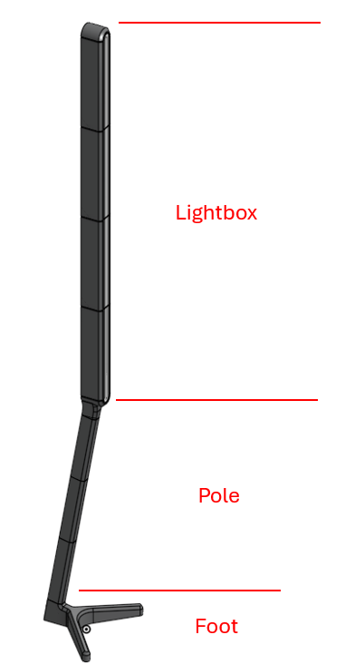
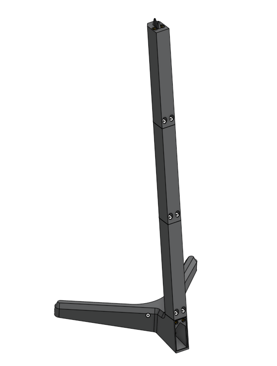
Below an exploded view of the entire setup.
- You have on one hand the Moody itself. This is the standing lamp that creates the mesmerizing effects. It is split up in three major sections:
- The foot
- The pole
- The lightbox
- On the other hand you have the HDMI box. This one connects your streaming device to your television screen and wirelessly broadcasts the tv colors to your Moody.
Note: The electronic wires are not visible in these 3D renderings. Wiring and soldering will be done later when assembling the top half of the base.
Preparations
Step 1: Insert nut melting. This you can do immediately after printing the parts. Use your soldering iron to melt the nuts in the correct holes. Watch out for following two things:
- Make sure no molten plastic enters the nut on the inside. This will contaminate the internal threads and you will not be able to mount a screw in. In between each insert placement, check your solder tip to make sure it is clean. If not, clean it.
- Most of the insert nuts are installed at a slope (the holes are angled compared to the print part). We made sure to expose a surface around the mount holes so you have this as a flat surface reference. Make sure to carefully align your solder iron with the hole (or hold it perpendicular to the reference surface). it helps to first place the nut in place, normally the narrower lip of the nut should slide into the hole already before applying heat.
- Make sure that the nut is flush with the reference surface and not installed too deep. If you mount it too deep, excess molten plastic might clog op the exit hole of the nut and your screw cannot go in all the way If you have not yet used heat insert nuts in 3D prints, this youtube video explains everything you need to now
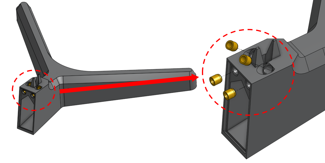
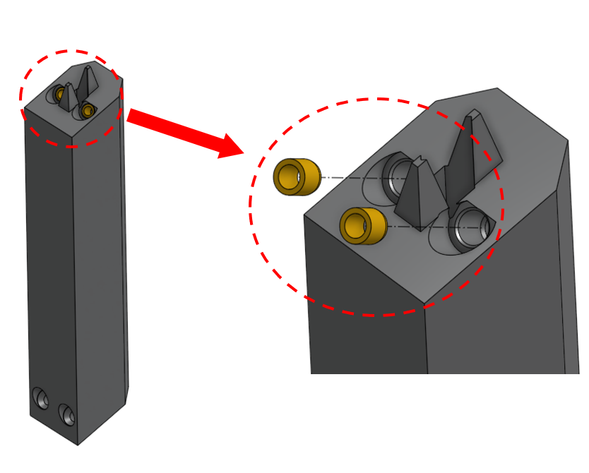
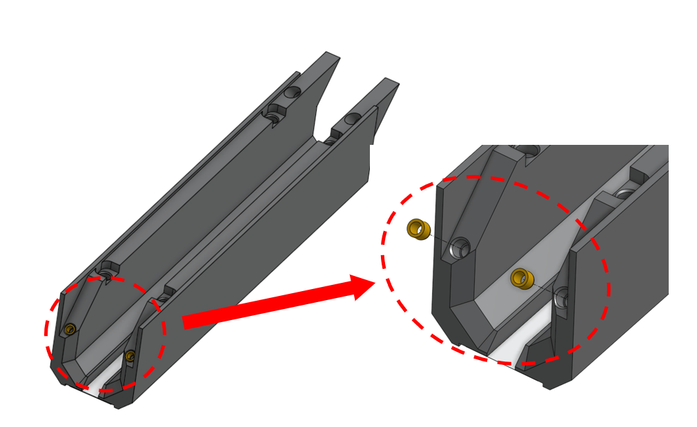
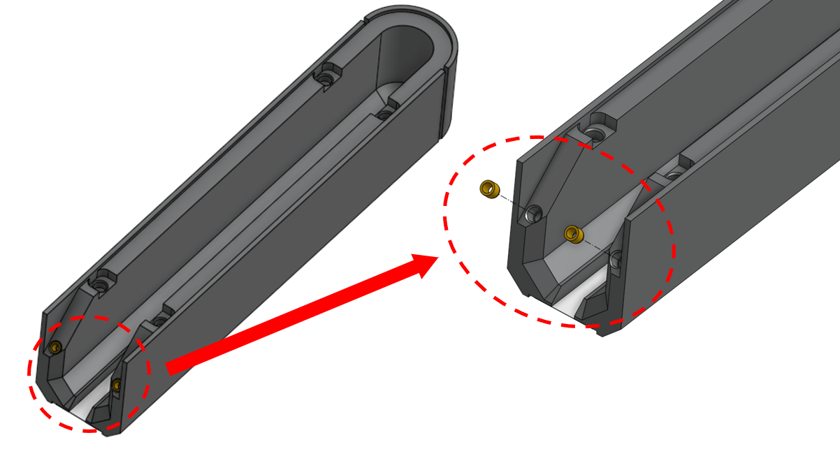
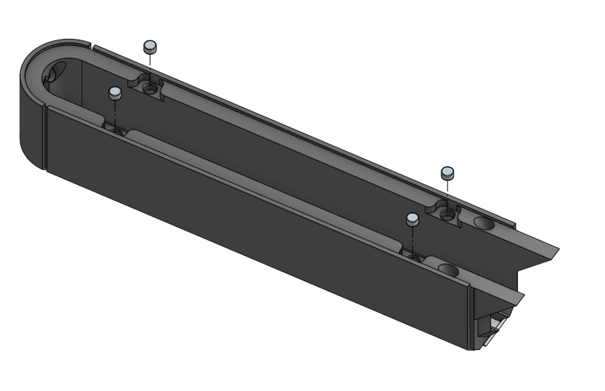
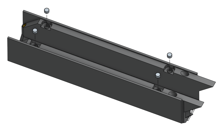
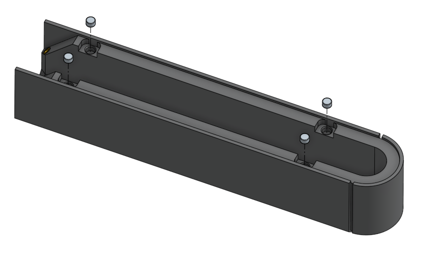
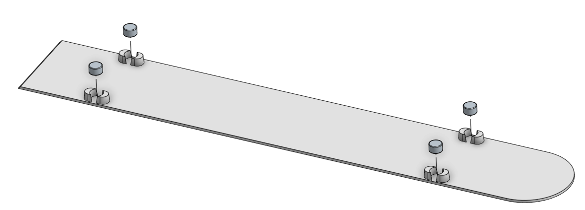
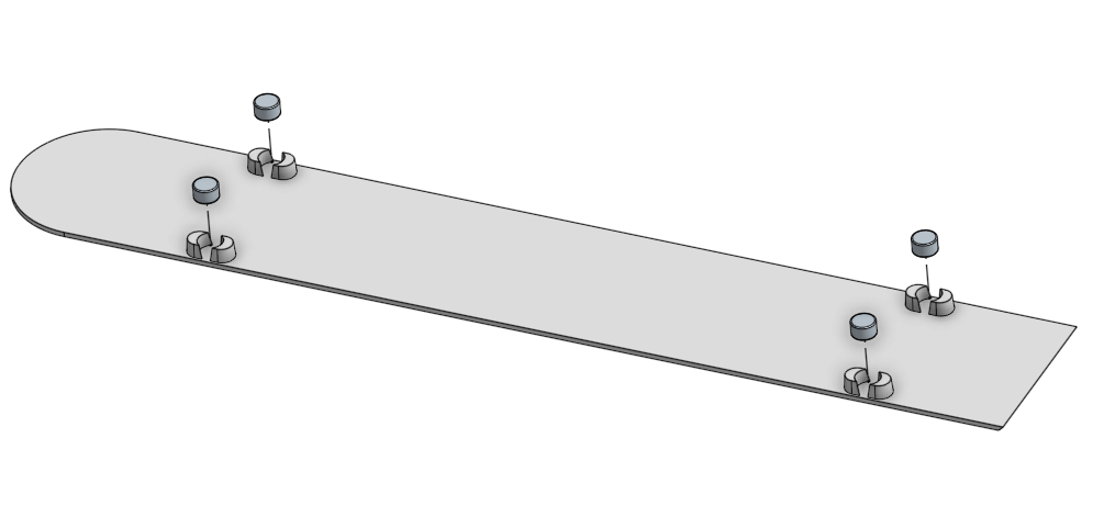
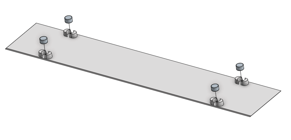
Below we'll show you where to install these insert nuts. Following print parts are shown:
- Foot
- Pole
- Pole connection lightbar
- Lightbox Middle
- Lightbox Top
Remark: Depending on your setup, you might have more pole segments or lightbox segments printed, resulting in more insert nut placements.

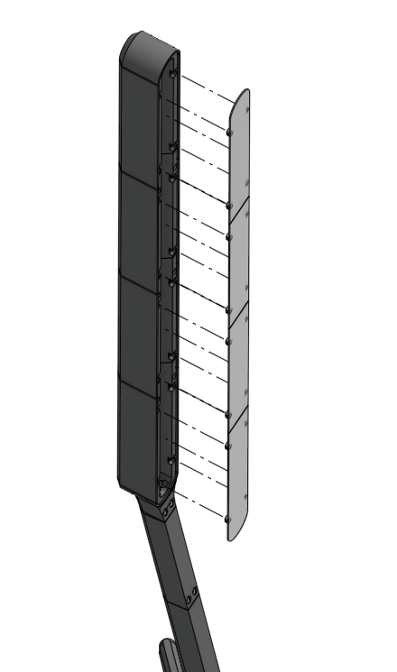
Step 2: Attach magnets. The backside of the lightbox has diffusor backplates that are attached using magnets. You can install these magnets immediately after you have printed these components. Just to be sure they never come off, apply a tiny droplet of glue (or hot glue) in the mount hole, before pressing them in. Make sure the magnets are oriented correctly.
Below we'll show you where to install the magnets. They show following print parts:
- Lightbox Bottom
- Lightbox Middle
- Lightbox Top
- Back Diffusor Bottom
- Back Diffusor Middle
- Back Diffusor Top
Remark: Make sure the magnets are all oriented correctly so that the diffusor backplates actually stick to the lightbox and are not repelled.
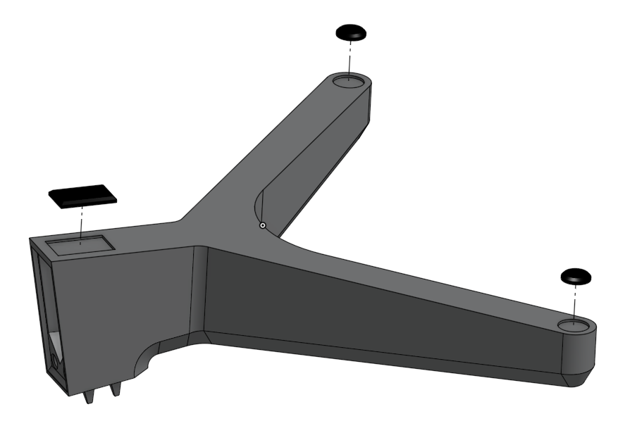
Step 3: Hot glue damper feet. Real simple, hot glue the 3D printed Foot dampers on the dedicated spots of the foot.
Assembly steps Moody
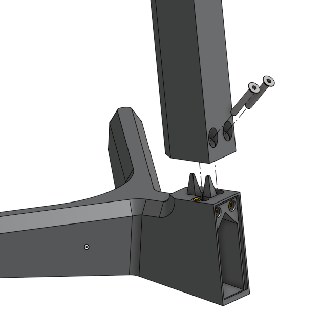
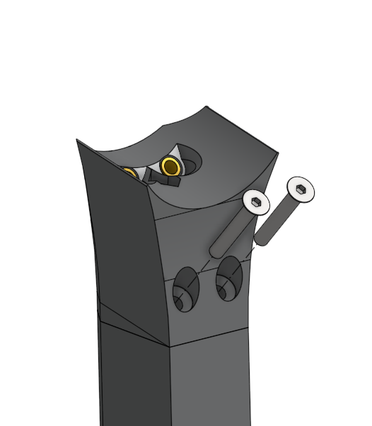
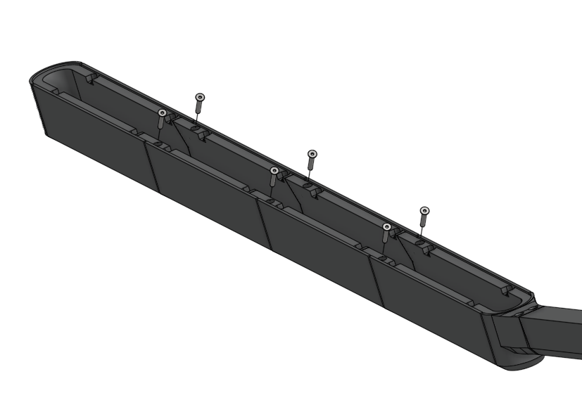
Step 4: Mount the poles on the foot. Use M3x20 countersunk screws. Slide a new pole segment in place and use the screws to permanently fixate them as seen in the pictures below. Do the same for the connection piece.
Remark: Do not use excessive force on the screws. If you notice some resistance on the screws even before the screw has reached its stop surface, it means something else is blocking the screw: the nut. If you try to force your way through, the nut will heat up and come loose. It is best to first unscrew and check if the insert nuts are flush with the reference surface or not contaminated. If the former seems to be the issue, it might help to gently reorient it with a soldering iron. Be sure not to get any plastic inside the nuts.
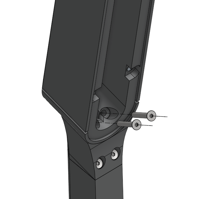
Step 5 : Connect all the lightbox segments to the pole using M3X20 countersunk screws.
Step 6 (In case you don't have a multicolor printer): Glue the front diffusors to the lightbox frame.
First connect the lightbox pieces similar as seen above, so you have one solid frame. Now it is easier to align and glue the front diffusor plates that you printed. You can use hot glue or other types of glue are compatible with PLA/plastics. Take your time to align everything. Make sure that no glue enters the clearance in between the lightbox segments. Now you will be able to take the segments apart if needed.
Step 7: Prepare the LED strip
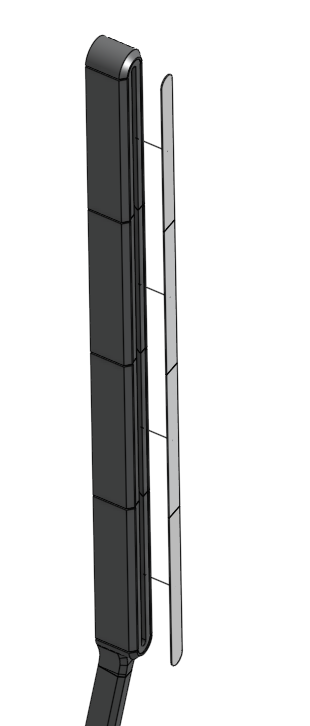
Cut the LED strip to the correct length. It should fit from top to bottom inside the lightbox (normally it has approximately the same height as your TV screen).
- After cutting the LED strip to the correct length, solder the three connection wires (5V, ground, and signal) to the strip.
- Use wires approximately ±650mm long. The wires will be guided through the pole to the hollow region in the foot. For your setup, this length might be different. Just take the total length of your pole plus an additional 100mm as overlength.
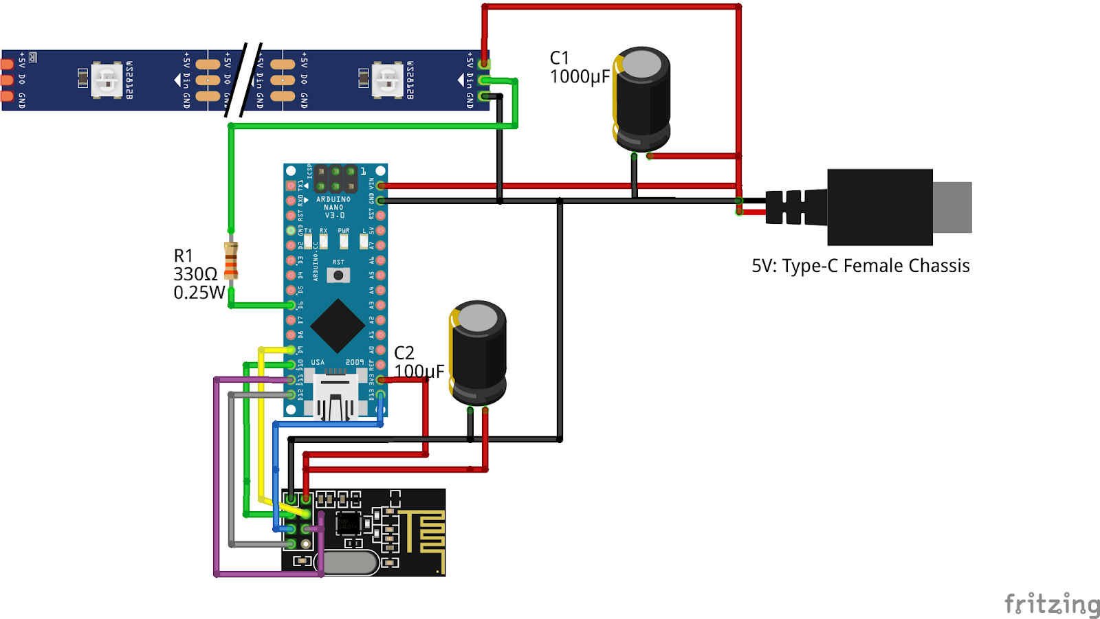
- Ensure proper polarity by soldering the wires to the start side of the LED strip. The arrows printed on the LED strip point away from the START (i.e., the opposite side). Check the Wiring Diagram in Step 10 for a visual explanation.
- Verify Direction: Electricity flows only in one direction through the LED strip, following the arrows. Ensure the wires are connected correctly to avoid functionality issues.
Remark: The copper pads on the led strips are tiny. It helps to use some small cut strips as practice. Be sure to gently tug on the soldered wires to ensure a proper connection is made. Sometimes it looks like it is soldered ok, but in fact, it is barely holding on.
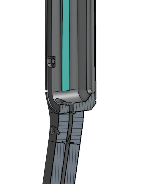
Step 8: Guide the led strip wires through the pole. The hole is small. It might help to unscrew some pole segments to guide the wires through in intervals. The wires should dangle with excessive loverlength out from the hole in the foot. This is okay, you will need this extra length in the soldering process. It will be tucked away later
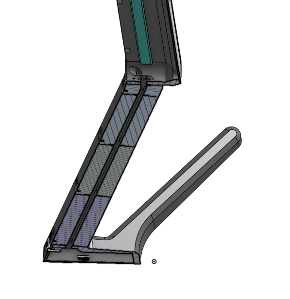
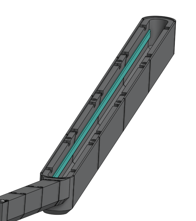
Step 9: Mount the led strip. Place it as shown below. You can place it either to the right or left inside the lightbox. Use tiny drops of hot glue at intervals of 50mm suffices to fixate the led strip. You can also use ducked tape if wanted, but this might loosen after a couple of months. But no worries, the back diffusor plates can be removed easily with the magnetic connections.
Step 10: Install the electronics
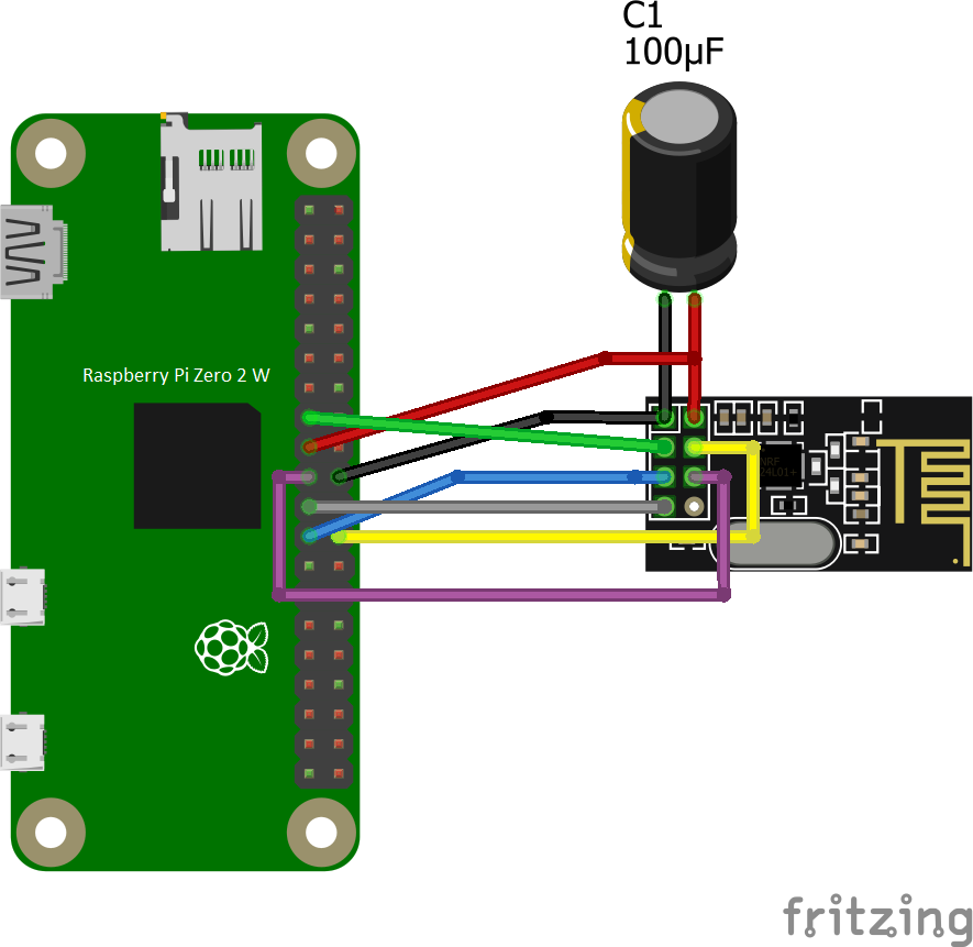
- Solder the electronics as shown in the diagram below. Make sure to use shrink sockets at the solder connections to protect it from short-circuiting.
- It is important to make the wires quiet short (try to stay below 50mm) otherwise they will take up too much volume and all the electronics will not fit in the cavity.
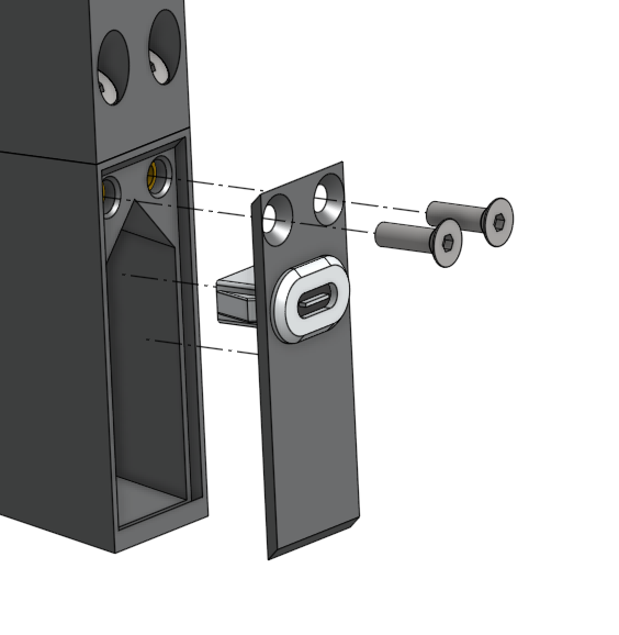
Remark: The USB C port should be clicked on the backplate already before soldering (see picture below).
- Flash the test software on the Arduino to make sure your everything is soldered correctly. Go to 07 Installing Moody Software for more in depth info.
- Flash the Moody software on the Arduino. Go to 07 Installing Moody Software for more info.
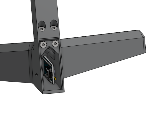
- Tug away all the electronics in the foreseen cavity. Mount the backplate on using M3X10 countersunk screws, closing everything off.
Step 11: Mount the diffusor backplates on the back side of the light box. Just snap them in place. The magnets will do their job. Start with the top one and go down.
Step 12: Yout first Moody is finished.
- Repeat all the steps for a second Moody to have one both left and right of your screen. Next you'll need to assemble the HDMI box. This is explained in next paragraph.
Assembly steps HDMI box
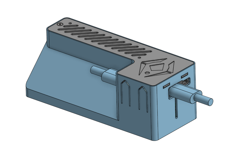
Overview
The HDMI box is the brains of the Moody lights. It is essentially a Raspberry Pi that reads the images your media device is sending to your monitor via HDMI cables. It copies the relevant pixels and sends this information wirelessly to your Moody light. All the components needed to read the HDMI information, process it, and send it to your Moody lamps are contained within a 3D-printed enclosure. The HDMI box is easy to assemble.
Remark 1: You can choose to not house everything in the enclosure and to have the raspberry and cables exposed and tucked away behind your screen. However, if you like everything neat and protected, it is better to follow all the steps below. It will not take long.
Remark 2: Not all cables are shown in the 3D images. Make sure to follow the wiring diagram in order to have everything connected properly.
Preparations
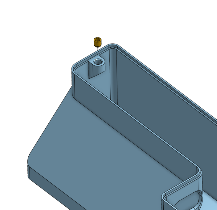
Step 13: Insert nut melting. At this point you know how to mount insert nuts. The enclosure only takes 1 screw to close as seen below. Insert the M3 nut in the 3D printed part called 'HDMI box enclosure'.
Assembly steps HDMI box
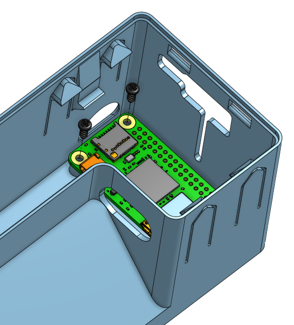
Step 14: Screw the Raspberry Pi ZERO W2 in place. This time we use self tapping screws. M2.6 x 6mm. Self tapping screws don't need nuts and can tighten themselves directly in the plastic holes in the studs from the hdmi enclosure as seen below.
Comment: The reason why we don't use self tapping screws often? They are simpler since they don't require the insert nut step. But they are not meant to unscrew and screw multiple times. The screw will loose grip over time and will not work anymore. It also can be pulled out more easily, so it is less reliable for load bearing connections. In this case, the raspberry simply needs to be hold in place (almost no force acquired) and the chances that you have to remove and reinstall the raspberry are slim.
Step 15: Connect the required cables to the raspberry PI.
- In this step, we insert the cables into the two micro USB ports. One cable is for power, and one is for connecting to the HDMI capture device. You can see in the wiring diagram below where to connect each cable. There’s no need to connect the other cables just yet—only the two cables for the micro USB ports on the Raspberry Pi.
- Bring the power cable to the outside of the enclosure and push it in the slot as seen below. (ignore the power splitter cable for now)
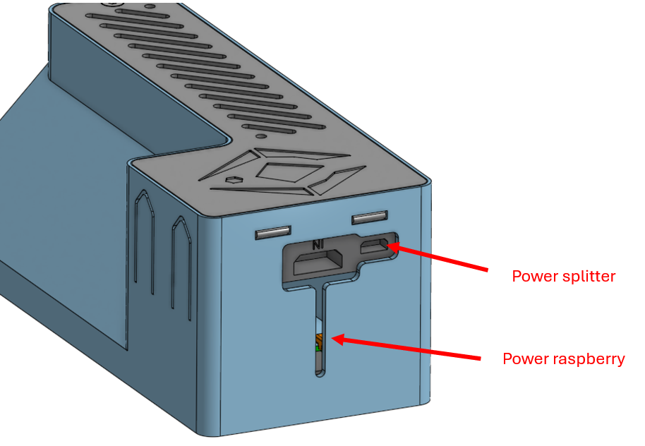
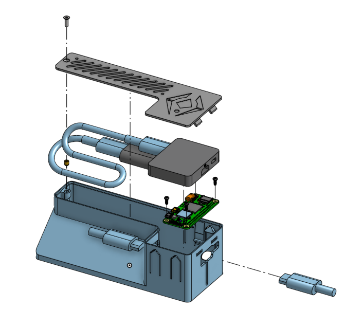
Step 16: Mount the splitter.
Click in place the HDMI splitter box. The snaps of the enclosure will hold it in place. No need to screw.
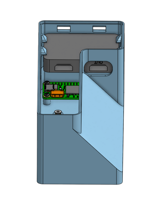
Step 17: Connect the remaining components:
- internal HDMI cable (short HDMI cable)
- HDMI capture device
Use the wiring diagram to connect everything (at the moment do not yet connect the external HDMI cables). Go to 06 Wiring Schemesfor more in depth info about the wiring.

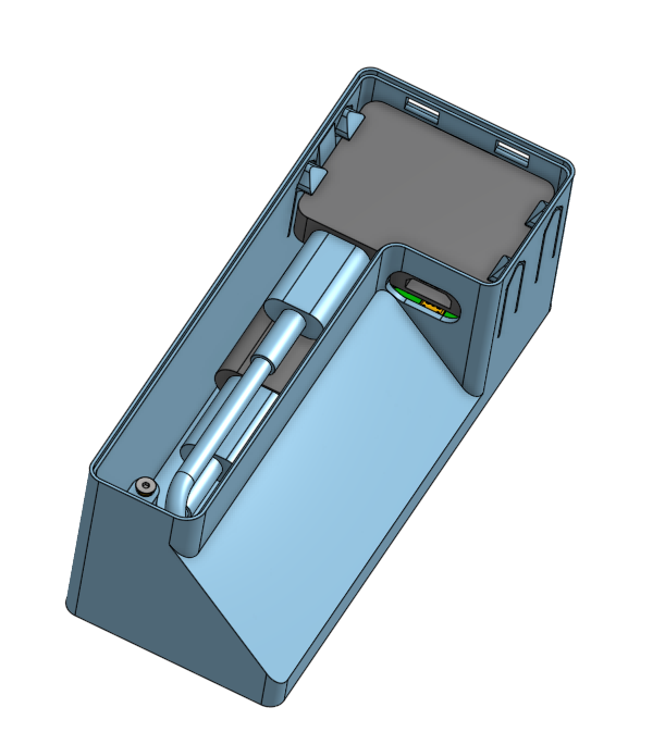
There is plenty of space in left inside the enclosure. You can see below how it might fit:
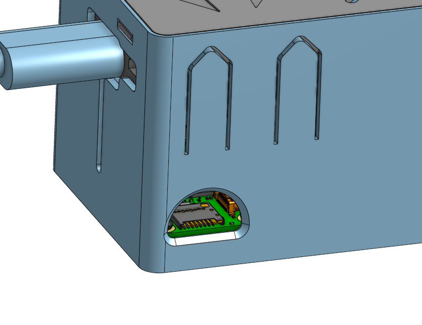
Step 18: Insert the micro sd card. Flash the operating system and software first. For more info how to install the software, see 07 Installing Moody Software. You can simply reach the micro sd-port from the opening in the enclosure.
Remark: Make sure that the raspberry is NOT powered when inserting the micro SD card. Vice Versa, always correctly shut down the Raspberry before removing power. Otherwise the micro SD-card might be corrupted.
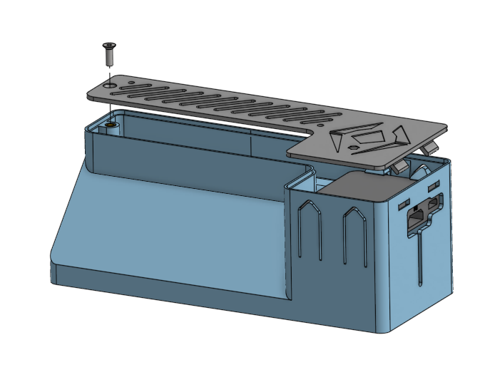
Step 19: Mount the 3D printed HDMI box lid on the enclosure to close everything off. Use M3x10 countersunk screws (longer ones also possible). First slide the pins in the holes on the right side and than on the other side mount the screw in place.
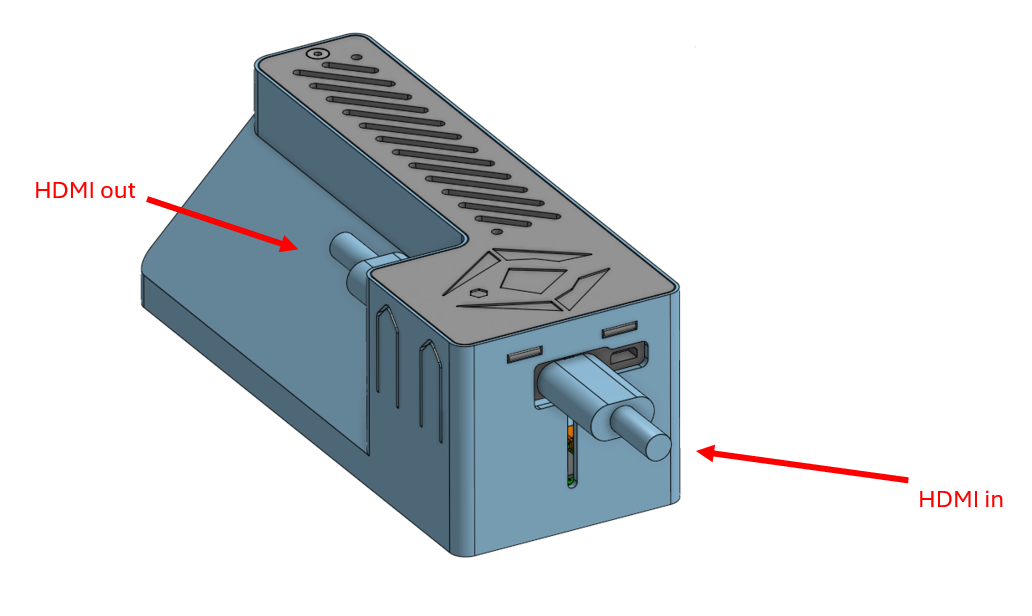
Step 20: connect the HDMI-box to your screen and media device with the HDMI cables.
- HDMI in: this is the HDMI cable coming from your media device
- HDMI out: this is the HDMI cable going to your monitor/tv-screen
Step 21: Enjoy! Now just simply power everything up and enjoy the magic!
Troubleshooting:
- The Moody lamps are unresponsive or low refresh rate? This means your USB A power brick is too weak. It needs a higher wattage. Try using a different power brick with higher wattage or order one online.
- The Moody lamps are portraying the colors of the wrong side of the tv? Simply switch the Moody lamps. You can unplug them and plug them in as much as you want. They will automatically connect with the raspberry once powered.
- One of the moody lamps is portraying the wrong side of the screen? Change one of the parameters in the arduino code. One of the parameters allocates a receiving end (Moody lamp) to the raspberry sending the colors. If this parameter is wrong, the raspberry is sending the wrong side of the television.
5. Assembly steps